 notes.uart.sh
All-in-one microUSB carkit UART debug cable
(…TODO, get a less unwieldy name for it.)
Backstory#
I work with a lot of Samsung smartphones from the early-mid 2010s; all of them have microUSB ports. For pretty much every single one of their devices, Samsung were kind enough to include an MUIC (MicroUSB IC) which allows for switching the cable mode based on the resistance between the ID and GND pins.
USB OTG is perhaps the best known of these “alternative modes”, but did you know that the “Carkit” standard defines way more modes - including UART? A 150 kOhm resistor causes D+ and D- to become RX and TX respectively (so, you plug them into TX and RX of a UART dongle):
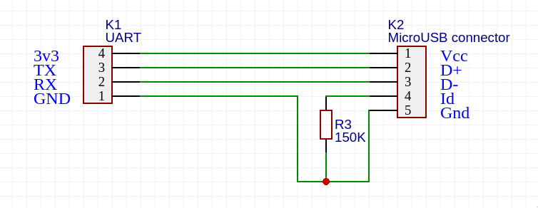

Samsung's devices also support two other modes that do the same thing - 529 kOhm is “factory mode boot OFF-UART”, and 619 kOhm is “factory mode boot ON-UART”.
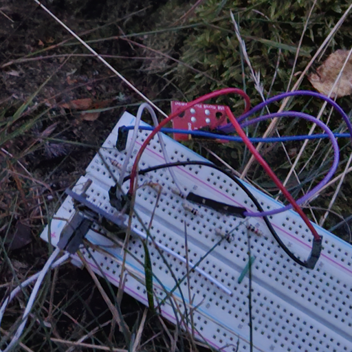
Up until now, my usual setup for USB debugging was this janky breadboard setup involving an FT232-powered USB UART chip, some resistors connected in series, and a SparkFun microUSB breakout board (much better than the tiny on-plug solder pads).
The main problem with it was that it was farily unwieldy. The breadboard is much bigger than the picture shows - it doesn't neatly fit in any small boxes for tossing into a bag, and not having it in a box would smoosh the cables going from the USB plug to the breadboard, forcing me to rummage around for more cables to use. (Sometimes I'd need to replace the cables even if they didn't show any signs of damage, or else it wouldn't work…)
It also had the downside of being separate from my regular USB cable, meaning the usual workflow for debugging would look something like this:
- Plug in a regular USB cable for flashing
- Reboot the device into flashing mode and flash the kernel I'm testing
- Once it flashes and reboots, plug in the serial cable for early-boot logs
My laptop only has one USB-A port (and two USB-C ports, one of which is broken, and for the other I lost my portable dock a while back… got another one since then though, but I digress). All the microUSB cables I own are USB-A to microUSB, and the UART board is also connected via microUSB, so the actual procedure looked something like this:
- Plug the microUSB out of the UART dongle and into the device for flashing
- After flashing, unplug microUSB from phone and move it to the UART dongle, then plug in the dongle's microUSB into the phone
- …and do it fast enough that I can capture early boot logs, otherwise I have to reboot the device and wait another half a minute…
Rinse and repeat dozens of times. It's a miracle I haven't ruined any microUSB ports (or cables…) yet[1].
Nonetheless, I persisted with that setup, until a silly mistake forced me to reconsider it. Remember when I said the breadboard was unwieldy to carry around? Yeah… I had to dismantle it to fit it in a smaller box (so the breadboard, USB UART and microUSB plug were all separate), but the plug didn't fit in the box I was planning to use, so I put it in a separate bag.
1 train journey and 100km later, I realized the bag was nowhere to be found.
The one component of the setup I could not trivially replace without a part order from abroad[2] and a visit to my nearest hackerspace.
Planning a replacement#
I'd been planning to create the debug cable of my dreams for a while now, but never got around to doing it (mostly due to my lack of expertise with PCB design, and not knowing who to ask…). Nonetheless, starting out is always the most difficult part, but if I was already going to be ordering parts, why not do it the right way around this time?
The general idea is as follows:
- We create a small PCB that can be plugged into a mobile device - it has a microUSB plug on the device end, and a USB-C socket on the host end.
- The cable can switch between two modes: USB passthrough and UART.
- In USB passthrough mode, the microUSB connection goes directly from the host to the device (in this case, it also acts as an USB-C to microUSB converter).
- In UART mode, the host connects to an onboard UART chip, which in turn connects TX/RX to D+/D- on the cable, as per the carkit schematics above.
- We also need to place a resistor between ID and GND; this is configurable between two common values - 150kOhm and 619kOhm - with a second onboard switch.
I made an initial schematic in LibrePCB, mostly just to figure out how to put the whole thing together, and came up with the following:
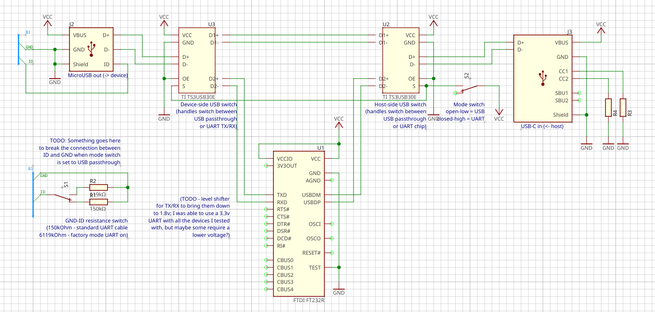
The USB mode switching is handled by a physical toggle switch that switches two USB switch ICs (TI TS3USB30E) and the connection between ID and GND in the resistor circuits. The resistance configuration is done with another switch. An onboard FTDI FT232R provides the UART functionality.
- ^
Can't say that about USB-C ports (see 2 paragraphs above).
- ^
If somebody who works at Botland is reading this, can you please stock up on SparkFun's microUSB breakout boards or equivalent? You have plenty of breakouts with microUSB sockets, and you have the microUSB plugs with those teeny tiny pads that are a pain to solder to and very easy to rip apart, but no breakout for a microUSB plug…